
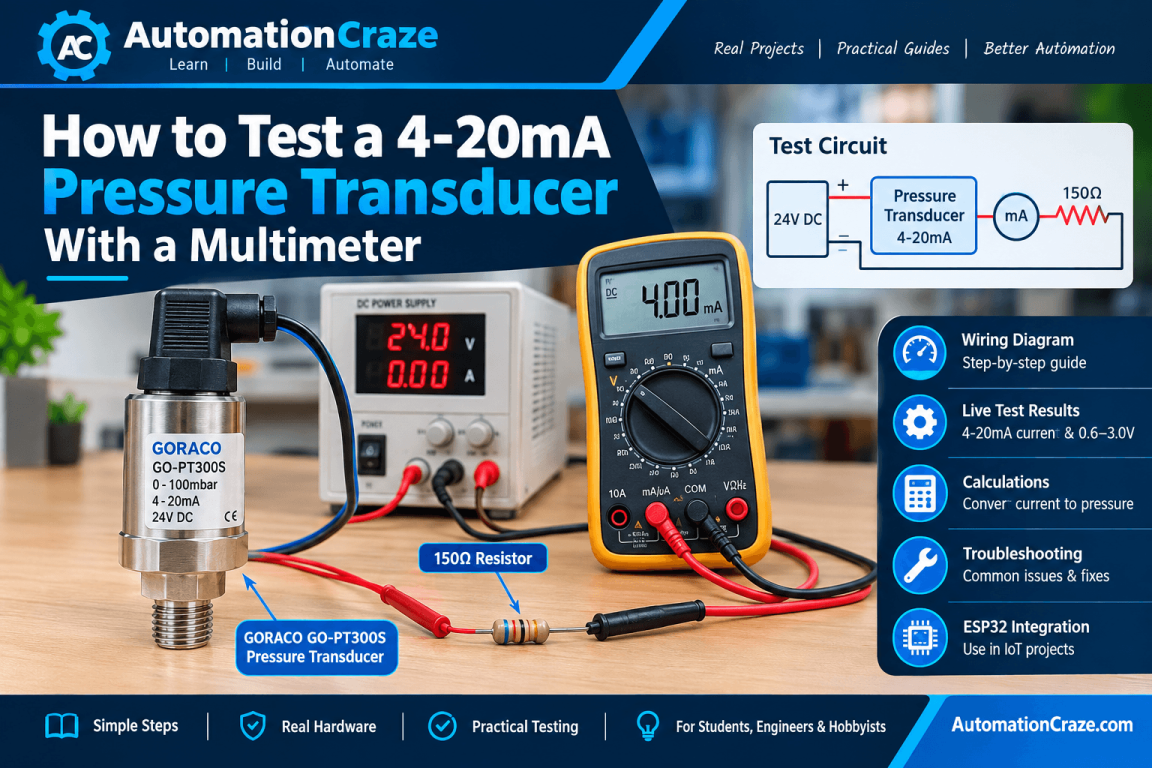
Testing a 4–20mA pressure transducer with a multimeter is a simple way to check whether the sensor is working correctly before connecting it to a PLC, controller, or other automation system.
In this practical guide, I am testing a GORACO GO-PT300S pressure transducer with a 0–100 mbar pressure range and a 4–20mA, 2-wire output. The test uses a 24V DC power supply, a 150Ω resistor, and a digital multimeter.
We will check the sensor’s 4–20mA output, apply pressure to the sensor, and measure the corresponding electrical signal. We will also see how the voltage across the 150Ω resistor can be used to verify the current output.
This practical test can help you confirm that a pressure transducer is working properly before using it in an industrial automation or instrumentation application.
Table of Contents
ToggleWhat You Will Learn
- What a 4–20mA pressure transducer is
- How a 2-wire 4–20mA pressure transducer works
- How to connect the sensor to a 24V DC power supply
- How to use a 150Ω resistor for testing
- How to measure the 4–20mA current with a multimeter
- How to measure voltage across the resistor
- How to calculate current from the measured voltage
- How to check whether the pressure transducer responds correctly to applied pressure
- How to troubleshoot common 4–20mA sensor problems
What Is a 4–20mA Pressure Transducer?
A pressure transducer converts pressure into an electrical signal. In industrial automation and instrumentation, 4–20mA is one of the most commonly used output signals.
For a typical 4–20mA pressure transducer:
- 4mA represents 0% of the pressure range
- 12mA represents 50% of the pressure range
- 20mA represents 100% of the pressure range
For our 0–100 mbar sensor:
| Pressure | Expected Output |
|---|---|
| 0 mbar | 4mA |
| 25 mbar | 8mA |
| 50 mbar | 12mA |
| 75 mbar | 16mA |
| 100 mbar | 20mA |
This relationship allows a PLC, controller, or other measuring device to determine the pressure from the sensor’s current output.
Why Use a 4–20mA Signal?
The 4–20mA signal is widely used in industrial automation and instrumentation because it provides reliable signal transmission, even over relatively long cable distances.
Another important advantage is the 4mA live zero. The signal does not start at 0mA. Instead, 4mA represents the lowest value of the measurement range.
This makes it easier to identify certain problems. For example, a reading close to 0mA may indicate a broken wire, loss of power, or another fault, while approximately 4mA normally represents zero pressure.
For our 0–100 mbar pressure transducer:
- 4mA = 0 mbar
- 12mA = 50 mbar
- 20mA = 100 mbar
This simple relationship makes 4–20mA sensors very useful for industrial pressure measurement and control systems.
Equipment Required
For this practical test, you will need the following equipment:
- GORACO GO-PT300S pressure transducer
- Pressure range: 0–100 mbar
- Output: 4–20mA
- Configuration: 2-wire
- 24V DC power supply
- Digital multimeter
- 150Ω resistor
- Connecting wires
- A suitable source of pressure for testing the sensor
The 150Ω resistor is particularly useful because it allows us to convert the 4–20mA current signal into a measurable voltage signal.
For example, when 4mA flows through a 150Ω resistor, the voltage across the resistor is 0.6V. At 20mA, the voltage becomes 3.0V.
Understanding the 150Ω Resistor
A 150Ω resistor can be used to convert the 4–20mA current signal from the pressure transducer into a voltage that can easily be measured with a multimeter.
We use Ohm’s Law:
V = I × R
Where:
- V = Voltage
- I = Current
- R = Resistance
With a 150Ω resistor:
- 4mA → 0.6V
- 8mA → 1.2V
- 12mA → 1.8V
- 16mA → 2.4V
- 20mA → 3.0V
This gives us a convenient 0.6V to 3.0V measurement range.
By measuring the voltage across the resistor, we can determine the current flowing through the 4–20mA loop and verify whether the pressure transducer is producing the expected output.
Wiring the 4–20mA Pressure Transducer
For this test, we use a 24V DC power supply, the pressure transducer, a 150Ω resistor, and a multimeter.
The basic current-loop connection is:
+24V DC → Pressure Transducer → Multimeter → 150Ω Resistor → 0V DC
The multimeter must be connected in series with the sensor when measuring the 4–20mA current.
For the GORACO GO-PT300S used in this test, connect the positive supply to the sensor’s V+ terminal and connect the signal terminal into the current loop.
Before applying power, carefully check the polarity and make sure all connections are secure.
Important: When the multimeter is set to measure current, never connect it directly across the 24V power supply. The meter can behave almost like a short circuit and may cause a short circuit or blow the meter’s fuse.
Step-by-Step Test
Now let’s test the pressure transducer step by step.
Step 1: Turn Off the Power
Switch off the 24V DC power supply before making any connections.
Check the wiring carefully and make sure the connections are secure.
Step 2: Connect the Positive Supply
Connect the +24V DC terminal of the power supply to the V+ terminal of the pressure transducer.
Step 3: Connect the Current Loop
Connect the sensor’s signal/output terminal into the current loop through the multimeter and the 150Ω resistor.
The complete circuit is:
+24V → Pressure Transducer → Multimeter → 150Ω Resistor → 0V
Step 4: Set the Multimeter to DC Current
Set the multimeter to DC current (mA) mode.
If your multimeter is not autoranging, select an appropriate milliampere range.
Make sure the meter leads are connected to the correct terminals for current measurement.
Step 5: Apply Power
Turn on the 24V DC power supply.
With little or no pressure applied, the sensor should produce a current close to 4mA.
In my practical test, the sensor initially produced approximately 4mA, indicating that it was powered and its output was at the lower end of its measurement range.
Applying Pressure to the Sensor
After confirming that the pressure transducer produces approximately 4mA with little or no applied pressure, the next step is to apply pressure to the sensor.
As pressure increases, the output current of the transducer should also increase. For a 0–100 mbar pressure transducer, the output should move from approximately 4mA at 0 mbar toward 20mA at 100 mbar.
The expected relationship is:
| Applied Pressure | Expected Output |
|---|---|
| 0 mbar | 4mA |
| 25 mbar | 8mA |
| 50 mbar | 12mA |
| 75 mbar | 16mA |
| 100 mbar | 20mA |
In my practical test, I applied pressure manually to the sensor and observed that the output increased from its initial reading.
This confirmed that the transducer was responding to the applied pressure.
The actual readings may vary slightly depending on the accuracy of the pressure source, multimeter, and pressure transducer.
Measuring Voltage Across the 150Ω Resistor
The 4–20mA signal can also be checked by measuring the voltage across the 150Ω resistor.
This is useful because we can use Ohm’s Law to convert the measured voltage back into the current flowing through the sensor loop.
The formula is:
V = I × R
With a 150Ω resistor, the expected voltage values are:
| Loop Current | Voltage Across 150Ω |
|---|---|
| 4mA | 0.6V |
| 8mA | 1.2V |
| 12mA | 1.8V |
| 16mA | 2.4V |
| 20mA | 3.0V |
For example, if the multimeter measures 1.8V across the resistor:
I = V ÷ R
I = 1.8 ÷ 150 = 0.012A
Therefore:
I = 12mA
For our 0–100 mbar pressure transducer, 12mA corresponds to approximately 50 mbar.
This gives us a second way to verify the sensor output without measuring the current directly.
Why the Sensor Starts at 4mA
You may wonder why the pressure transducer outputs 4mA instead of 0mA when there is no pressure.
This is because the sensor uses a 4–20mA live-zero signal.
The 4mA signal represents the minimum value of the sensor’s measurement range, while 20mA represents the maximum value.
For our 0–100 mbar pressure transducer:
- 4mA = 0 mbar
- 8mA = 25 mbar
- 12mA = 50 mbar
- 16mA = 75 mbar
- 20mA = 100 mbar
The advantage of using 4mA as the zero point is that a signal near 0mA can indicate a problem such as a broken wire, loss of power, or an open circuit.
So, seeing approximately 4mA with zero pressure is normal and is actually an important feature of the 4–20mA standard.
How to Calculate Pressure From Current
Once you know the current output from the pressure transducer, you can calculate the approximate pressure represented by that current.
For a 0–100 mbar sensor with a 4–20mA output, use this formula:
Pressure = (Current − 4) ÷ 16 × 100
For example, if the measured current is 12mA:
Pressure = (12 − 4) ÷ 16 × 100
Pressure = 50 mbar
Therefore, 12mA represents approximately 50 mbar for this particular pressure transducer.
The same formula can be used for any current between 4mA and 20mA, as long as the sensor has a linear 0–100 mbar range.
Troubleshooting a 4–20mA Pressure Transducer
If the pressure transducer does not produce the expected 4–20mA signal, there are several things you can check before assuming that the sensor is faulty.
Sensor Remains at Approximately 4mA
If the sensor remains close to 4mA even when pressure is applied, check:
- Is pressure actually reaching the sensor?
- Is the pressure port blocked?
- Is the applied pressure within the sensor’s specified range?
- Is the sensor wired correctly?
- Is pressure being applied to the correct port?
- Is the sensor responding mechanically to pressure?
Current Is 0mA
A reading of 0mA can indicate:
- Incorrect wiring
- An open circuit
- No power supply
- Incorrect multimeter connection
- A blown multimeter fuse
- A faulty pressure transducer
Check the complete current loop from the 24V power supply → sensor → multimeter → resistor → 0V.
Current Is Higher Than Expected
If the measured current is significantly higher than expected, check:
- The applied pressure
- The sensor’s pressure range
- Wiring and polarity
- Power supply voltage
- Multimeter settings
- Possible sensor damage
Always compare your measured values with the pressure range and specifications of the particular transducer you are testing.
Practical Test Results
In my practical bench test, I used a GORACO GO-PT300S pressure transducer with a 0–100 mbar range and 4–20mA output.
The sensor was connected to a 24V DC power supply and tested using a digital multimeter and a 150Ω resistor.
With little or no pressure applied, the sensor produced approximately 4mA.
I then applied pressure manually to the sensor and observed that the output current increased. This showed that the transducer was responding to the applied pressure rather than remaining fixed at its minimum output.
The 150Ω resistor also provides a convenient way to verify the current signal by measuring the voltage across it.
For example:
- 4mA → 0.6V
- 12mA → 1.8V
- 20mA → 3.0V
These values can be calculated using Ohm’s Law:
V = I × R
This simple test provides a practical way to confirm that the pressure transducer is powered correctly and responding to changes in pressure.
Connecting the Sensor to a PLC or Controller
After confirming that the pressure transducer is working correctly, the 4–20mA output can be connected to a suitable PLC, controller, data acquisition system, or other industrial automation equipment.
Many PLCs and industrial controllers have dedicated 4–20mA analog input channels. The controller measures the current and converts it into a corresponding pressure value.
For our 0–100 mbar sensor:
- 4mA → 0 mbar
- 12mA → 50 mbar
- 20mA → 100 mbar
A 150Ω resistor can also be used when a voltage signal is required. It converts the 4–20mA signal into approximately 0.6–3.0V.
For example:
4mA × 150Ω = 0.6V
20mA × 150Ω = 3.0V
This voltage can be measured by an appropriate analog input, provided that the input’s voltage range is compatible with the generated signal.
Before connecting the sensor to any PLC or controller, always check the device’s wiring requirements, input type, supply voltage, and maximum permitted signal range.
Common Mistakes When Testing 4–20mA Sensors
When testing a 4–20mA pressure transducer, a few simple mistakes can lead to incorrect readings or even damage to the equipment.
Connecting the Multimeter in Parallel
When measuring current, the multimeter must be connected in series with the circuit.
Do not connect a multimeter set to current mode directly across the 24V power supply. This can create a short circuit and may blow the meter’s fuse.
Using the Wrong Multimeter Terminals
Most digital multimeters have separate terminals for measuring current.
Make sure the test leads are plugged into the correct mA/current terminal and COM terminal before measuring the sensor output.
Forgetting the Multimeter Fuse
If the multimeter suddenly reads 0mA even though the wiring appears correct, check the meter’s internal current fuse.
Using the Wrong Supply Voltage
Always check the pressure transducer’s required supply voltage before connecting it.
In this practical test, a 24V DC power supply was used.
Reversing the Sensor Connections
A 2-wire 4–20mA pressure transducer normally requires the correct polarity.
Always follow the terminal markings and the manufacturer’s wiring information.
Applying Pressure Beyond the Sensor Range
Our sensor has a 0–100 mbar measurement range. Do not apply pressure beyond the sensor’s specified limits, as excessive pressure can damage the transducer.
Conclusion
Testing a 4–20mA pressure transducer with a multimeter is a simple and practical way to verify that the sensor is working correctly before connecting it to a PLC, controller, or other automation equipment.
In this test, I used a GORACO GO-PT300S pressure transducer with a 0–100 mbar pressure range and 4–20mA, 2-wire output. The sensor was powered using a 24V DC supply and tested with a digital multimeter and 150Ω resistor.
With little or no applied pressure, the sensor produced approximately 4mA. When pressure was applied, the output current increased, confirming that the transducer was responding to changes in pressure.
The 150Ω resistor also provides a convenient way to verify the current signal by measuring voltage across the resistor:
- 4mA = 0.6V
- 12mA = 1.8V
- 20mA = 3.0V
This simple bench test can help identify wiring problems, power-supply issues, incorrect multimeter connections, and faulty sensor behavior before the transducer is installed in a real automation system.
If you work with industrial pressure sensors, understanding how to test a 4–20mA signal is a valuable troubleshooting skill and can save considerable time during installation and maintenance.