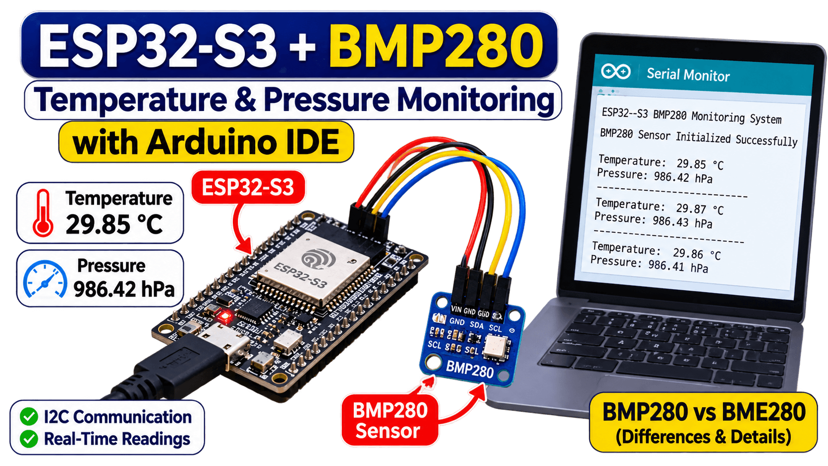
Have you ever wanted to measure temperature and atmospheric pressure using a microcontroller? With the ESP32-S3 and BMP280 sensor, you can build a simple and effective environmental monitoring system using just a few hardware connections.
In this tutorial, we will learn how to interface the BMP280 temperature and pressure sensor with the ESP32-S3 development board using Arduino IDE.
The BMP280 is a digital environmental sensor developed by Bosch Sensortec. It communicates with microcontrollers through I2C or SPI communication interfaces and provides reliable temperature and atmospheric pressure measurements.
You may also come across another popular sensor called the BME280. Although both sensors look similar and share many features, the BME280 offers an additional humidity measurement.
In this tutorial, we will first understand the difference between BMP280 and BME280. After that, we will perform a practical experiment using our actual BMP280 sensor connected to an ESP32-S3 development board.
We will configure I2C communication, identify the sensor address, verify its chip ID, write the Arduino program and display live temperature and pressure readings directly on our laptop using the Arduino IDE Serial Monitor.
This project is an excellent starting point for beginners interested in ESP32 programming, Arduino development, sensor interfacing and IoT applications.
Table of Contents
ToggleUnderstanding BMP280 and BME280 Sensors
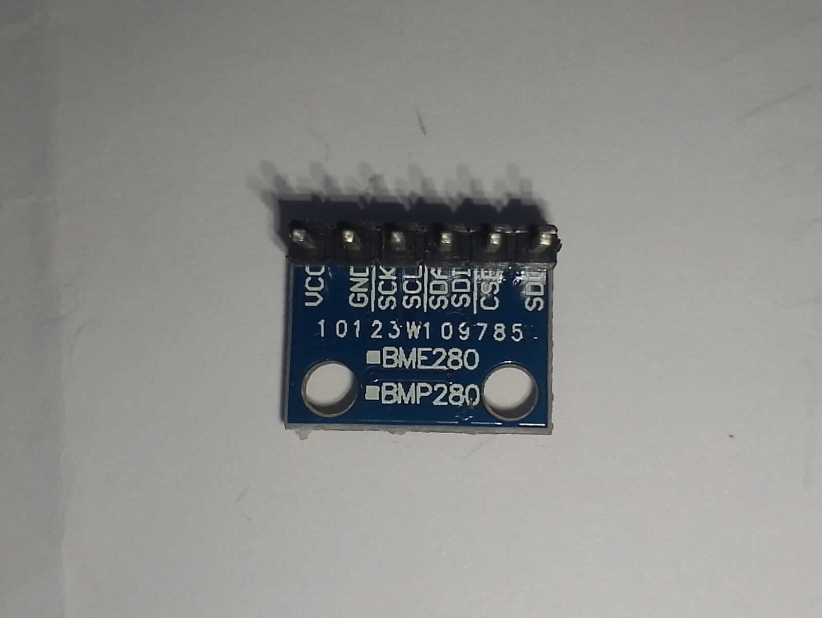
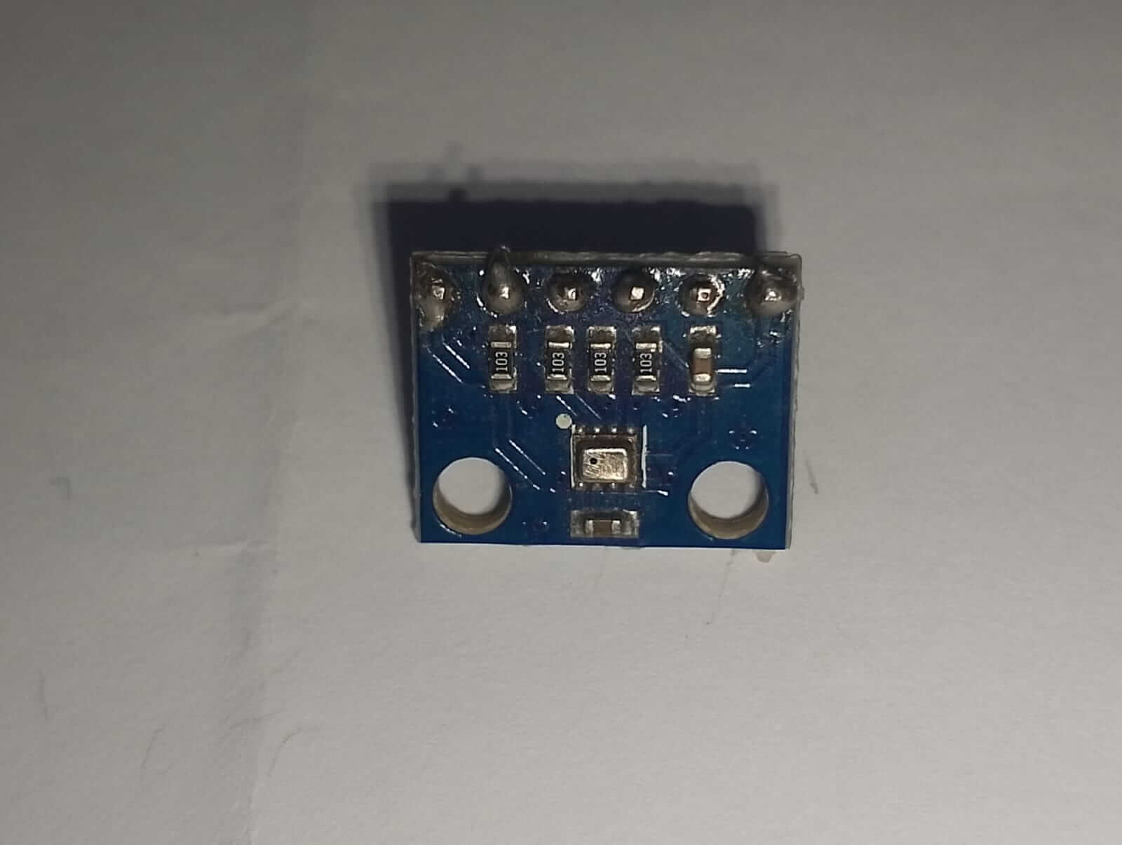
Before starting the practical experiment, let’s understand the difference between these two commonly used environmental sensors.
Both BMP280 and BME280 are manufactured by Bosch Sensortec. They are compact digital sensors designed for environmental monitoring applications.
However, they do not measure exactly the same parameters.
BMP280 Sensor
The BMP280 measures two environmental parameters:
Temperature
Atmospheric pressure
It is commonly used in weather monitoring systems, altitude measurement applications and environmental monitoring projects.
BME280 Sensor
The BME280 measures three environmental parameters:
Temperature
Atmospheric pressure
Relative humidity
It offers an additional humidity measurement, making it suitable for applications where all three environmental parameters are required.
Main Differences Between BMP280 and BME280
| Feature | BMP280 | BME280 |
|---|---|---|
| Temperature | Yes | Yes |
| Atmospheric Pressure | Yes | Yes |
| Relative Humidity | No | Yes |
| I2C Communication | Yes | Yes |
| SPI Communication | Yes | Yes |
| Typical I2C Addresses | 0x76 / 0x77 | 0x76 / 0x77 |
| Chip ID | 0x58 | 0x60 |
Which sensor are we using in this project?
For our practical experiment, we are using the BMP280 sensor.
Although the BME280 is also a popular choice for environmental monitoring, our actual hardware setup and testing have been performed using BMP280.
The good news is that the basic I2C wiring arrangement is the same for both sensors when using compatible breakout modules. However, their chip IDs and software libraries differ.
Now let’s move towards our practical implementation.
Components Required
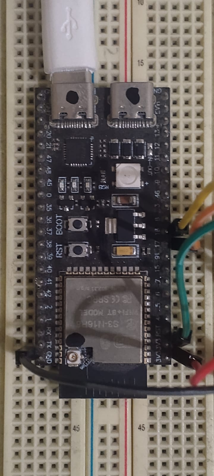
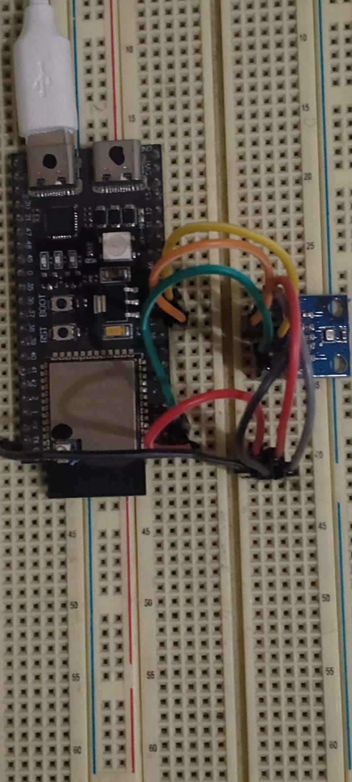
For this experiment, we need the following hardware and software.
Hardware Components
| Component | Quantity |
|---|---|
| ESP32-S3 Development Board | 1 |
| BMP280 Sensor Module | 1 |
| Jumper Wires | As required |
| USB Data Cable | 1 |
| Computer or Laptop | 1 |
Software Requirements
- Arduino IDE
- ESP32 Board Package for Arduino IDE
- Adafruit BMP280 Library
- Adafruit Unified Sensor Library
You can download Arduino IDE from the official website:
How Does the BMP280 Communicate with ESP32-S3?
The BMP280 supports two communication protocols:
- I2C (Inter-Integrated Circuit)
- SPI (Serial Peripheral Interface)
For our project, we will use I2C communication because it requires only two signal wires.
These are:
SDA (Serial Data): Transfers data between the ESP32-S3 and BMP280 sensor.
SCL (Serial Clock): Provides the clock signal required for synchronized communication.
The BMP280 typically uses one of two I2C addresses:
- 0x76
- 0x77
The actual address depends on the configuration of the sensor module.
The ESP32-S3 offers flexible GPIO configuration, allowing us to select suitable pins for I2C communication.
For our project, we will use GPIO 18 and GPIO 17.
Connecting BMP280 with ESP32-S3
As explained earlier, the basic I2C wiring arrangement is similar for BMP280 and BME280 modules.
Since we are using BMP280, connect the sensor to the ESP32-S3 according to the following table.
| BMP280 Pin | ESP32-S3 Pin |
|---|---|
| VCC | 3.3V |
| GND | GND |
| SDA | GPIO 18 |
| SCL | GPIO 17 |
Make sure all connections are secure before powering the board.
Important: We are powering our BMP280 module using the 3.3V supply from the ESP32-S3. Always check the voltage requirements of your particular breakout module.
Setting Up Arduino IDE for ESP32-S3
Before writing the program, we need to configure Arduino IDE to work with our ESP32-S3 development board.
Step 1: Install Arduino IDE
Download and install Arduino IDE from:
https://www.arduino.cc/en/software
Launch the software after installation.
Step 2: Install ESP32 Board Support
Open Arduino IDE and navigate to:
File → Preferences
Locate the Additional Boards Manager URLs field and add the official Espressif ESP32 board package URL:
https://espressif.github.io/arduino-esp32/package_esp32_index.json
Click OK.
Now open:
Tools → Board → Boards Manager
Search for ESP32 and install the package provided by Espressif Systems.
Step 3: Select Your ESP32-S3 Board
Connect your ESP32-S3 development board to your computer using a USB data cable.
Navigate to:
Tools → Board → ESP32 Arduino
Select the appropriate ESP32-S3 board profile. In our case, we are using ESP32-S3 DevKitC-1.
Next, select the correct COM port from:
Tools → Port
The COM port number may vary depending on your computer.
Installing the Required BMP280 Library
To communicate with the BMP280 sensor, we will use the Adafruit BMP280 library.
Open Arduino IDE and navigate to:
Sketch → Include Library → Manage Libraries
Search for and install:
- Adafruit BMP280 Library
This library provides the functions required to initialize the BMP280 and retrieve temperature and pressure readings.
- Adafruit Unified Sensor Library
This library provides a common sensor interface used by several Adafruit sensor libraries.
Once both libraries are installed, we are ready to communicate with the BMP280 sensor.
Scanning the I2C Address of BMP280
After uploading the program:
- Open Tools → Serial Monitor.
- Set the baud rate to 115200.
- Observe the scanning results.
Our Actual I2C Scanning Result
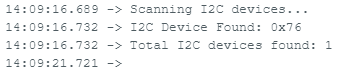
During our practical experiment, the ESP32-S3 successfully detected the connected BMP280 sensor.
The Serial Monitor displayed:
14:09:16.689 -> Scanning I2C devices...
14:09:16.732 -> I2C Device Found: 0x76
14:09:16.732 -> Total I2C devices found: 1
Our BMP280 sensor was detected at I2C address 0x76.
This confirmed that the physical wiring and I2C communication were working correctly.
Verifying the BMP280 Sensor Using Its Chip ID

Detecting an I2C device does not always tell us exactly which sensor is connected.
BMP280 and BME280 modules can use the same I2C address. Therefore, we can read the sensor’s chip identification register to distinguish between them.
The chip ID register is located at address 0xD0.
The identification values are:
- BMP280: 0x58
- BME280: 0x60
For our experiment, we used the following program to identify the connected sensor.
5:00:58.903 -> Checking BMP280 Sensor...
15:00:59.002 -> Chip ID: 0x58
15:00:59.002 -> RESULT: BMP280 DETECTED
15:00:59.002 -> Supports Pressure and Temperature only.
This confirmed that our connected sensor was a BMP280.
The chip ID verification was an important step because it confirmed the actual sensor type instead of relying only on the module’s appearance or I2C address.
Writing the Arduino Program to Read Temperature and Pressure
Now that we have successfully identified our BMP280 sensor, it is time to retrieve actual temperature and atmospheric pressure readings.
We will use the Adafruit BMP280 library to initialize the sensor and read its measurements.
Upload the following complete Arduino program:
The Output on Serial Monitor is:
15:40:35.181 -> BMP280 Sensor Initialized Successfully!
15:40:35.181 ->
15:40:35.181 -> Temperature: 27.64 °C
15:40:35.216 -> Atmospheric Pressure: 994.59 hPa

Understanding the Arduino Code
Let’s understand the important parts of our program.
Including Libraries
#include <Wire.h>
#include <Adafruit_Sensor.h>
#include <Adafruit_BMP280.h>
The Wire library handles I2C communication, while the Adafruit libraries provide the functions needed to communicate with the BMP280 sensor.
Defining I2C Pins
#define SDA_PIN 18
#define SCL_PIN 17
We have selected GPIO 18 for SDA and GPIO 17 for SCL, matching our physical connections.
Initializing the Sensor
if (!bmp.begin(0x76))
This command initializes the BMP280 sensor using its detected I2C address, 0x76.
If the sensor cannot be initialized, the program displays an error message.
Reading Temperature
float temperature = bmp.readTemperature();
This function reads the temperature measured by the BMP280 and returns the result in degrees Celsius.
Reading Atmospheric Pressure
float pressure = bmp.readPressure() / 100.0F;
The BMP280 library returns pressure in Pascals (Pa).
Dividing the value by 100 converts it into hectopascals (hPa).
Updating the Readings
delay(2000);
This command creates a two-second interval between successive readings.
Displaying Temperature and Pressure on Your Laptop
After uploading the program successfully, open the Arduino IDE Serial Monitor.
Make sure the baud rate is set to:
115200
You should now see temperature and atmospheric pressure readings appearing on your laptop.
An example output is shown below:
ESP32-S3 BMP280 Monitoring System
BMP280 Sensor Initialized Successfully
Temperature: 29.85 °C
Pressure: 986.42 hPa
—————————
Temperature: 29.87 °C
Pressure: 986.43 hPa
—————————
Temperature: 29.86 °C
Pressure: 986.41 hPa
—————————
Congratulations! You have successfully interfaced the BMP280 sensor with ESP32-S3 and displayed live temperature and atmospheric pressure readings on your computer.
Common Problems and Troubleshooting
Sometimes, the sensor may not communicate correctly with the ESP32-S3. Here are some common problems and their possible solutions.
| Problem | Possible Solution |
|---|---|
| No I2C device found | Check SDA, SCL, VCC and GND connections |
| BMP280 not detected | Check the I2C address (0x76 or 0x77) |
| Sensor initialization failed | Verify wiring, address and installed libraries |
| Incorrect Serial Monitor output | Check the baud rate (115200) |
| Uploading error | Check the selected board and COM port |
Troubleshooting tip: If your I2C scanner detects the sensor at 0x77 instead of 0x76, change the initialization command to:
bmp.begin(0x77);
Also, close the Arduino Serial Monitor before opening another serial application that needs to use the same COM port.
What Have We Achieved?
In this practical experiment, we successfully completed the first stage of our ESP32-S3 environmental monitoring project.
We have:
- Connected the BMP280 sensor to ESP32-S3.
- Configured I2C communication using GPIO 18 and GPIO 17.
- Detected the sensor at I2C address 0x76.
- Verified the BMP280 chip ID (0x58).
- Installed the required Arduino libraries.
- Programmed the ESP32-S3 using Arduino IDE.
- Retrieved temperature and atmospheric pressure readings.
- Displayed live sensor data on our laptop.
This project demonstrates how easily an ESP32-S3 can communicate with a digital environmental sensor.
Conclusion
Interfacing the BMP280 sensor with ESP32-S3 using Arduino IDE is a simple yet valuable project for anyone interested in electronics, embedded systems and IoT development.
Although BMP280 and BME280 share similar communication interfaces, understanding their differences is important when selecting the right sensor for an application.
The BMP280 is suitable for temperature and atmospheric pressure monitoring, while the BME280 provides an additional humidity measurement.
By completing this tutorial, you have learned how to establish I2C communication, identify a sensor address, verify the sensor chip ID, retrieve digital measurements and display real-time data on a computer.