
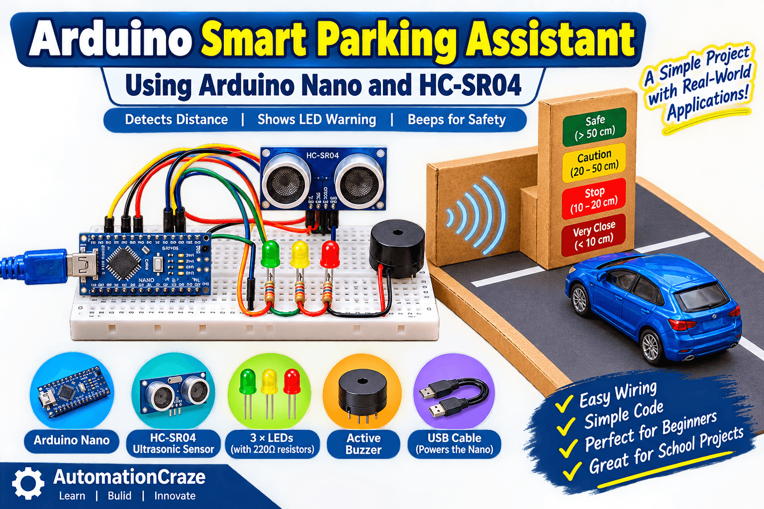
Have you ever wondered how modern cars detect obstacles while parking? An Arduino Smart Parking Assistant is a simple electronics project that demonstrates how sensors can help drivers park their vehicles more safely.
In this project, we will build an Arduino Smart Parking Assistant using Arduino Nano, an HC-SR04 ultrasonic sensor, three LEDs, and an active buzzer. The system measures the distance between a vehicle and an obstacle. Based on the measured distance, it displays a green, yellow, or red warning light and produces audible alerts when the vehicle gets too close to an obstacle.
This project is ideal for students, beginners, hobbyists, and anyone learning Arduino, electronics, and embedded systems.
By completing this project, you will learn how to connect an ultrasonic sensor to an Arduino Nano, control LEDs, generate buzzer alerts, and display sensor readings using the Arduino Serial Monitor.
Table of Contents
ToggleWhat You will learn
How an HC-SR04 ultrasonic sensor measures distance.
How to connect an HC-SR04 sensor to an Arduino Nano.
How to control three LEDs using Arduino digital pins.
How to generate slow and fast warning beeps with an active buzzer.
How to write and upload Arduino code.
How to test and demonstrate a smart parking system.
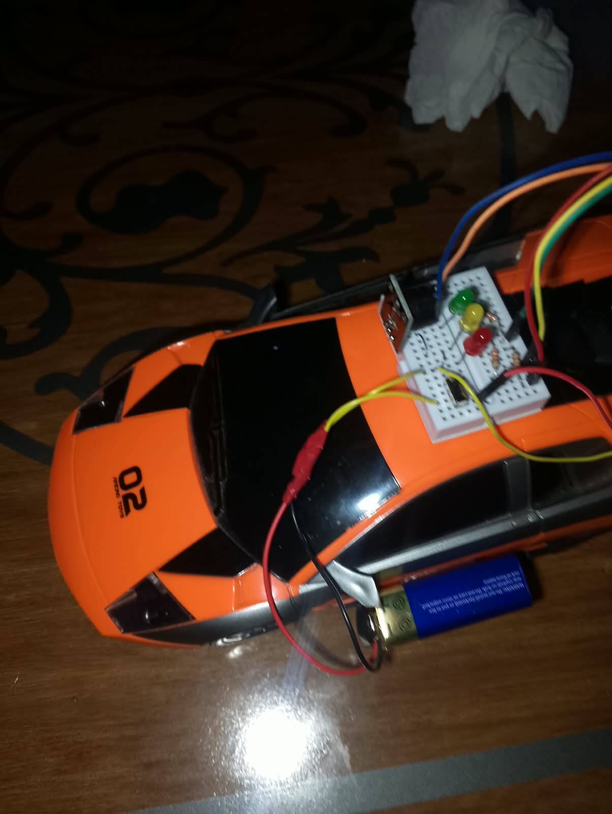
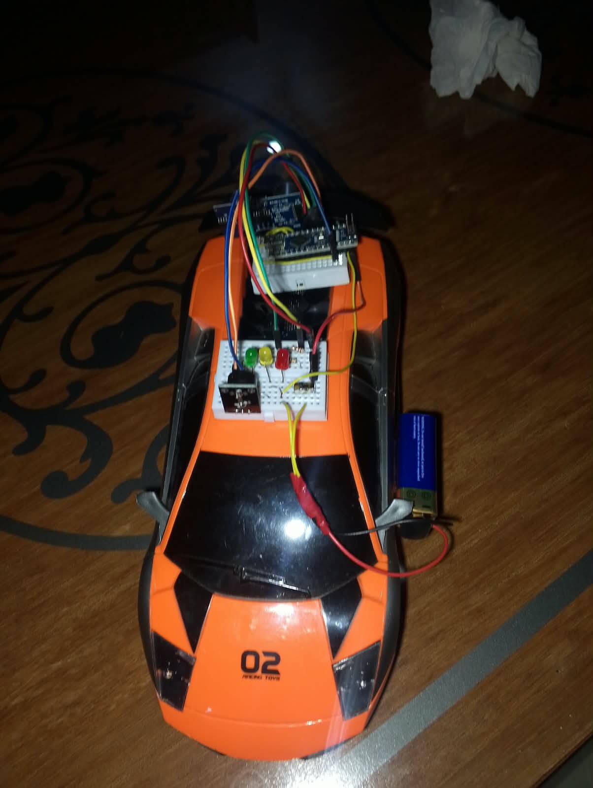
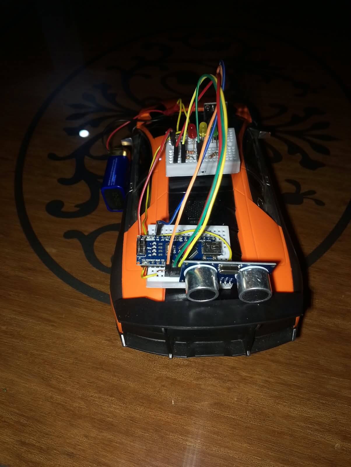
Toggle Button is used to Start the Car.
9V Battery is used as energy source, you can use cell or adapter as well.
When there is no obstacle, green light glow.
When there is an obstacle but at safe distance, yellow light will glow.
When distance is very narrow, red light will blink and a buzzer will sound to warm driver about obstacle behind.
Components Required
Before starting the project, collect the following electronic components.
| Component | Quantity | Purpose |
|---|---|---|
| Arduino Nano V3 | 1 | Main controller |
| HC-SR04 Ultrasonic Sensor | 1 | Measures obstacle distance |
| Green LED | 1 | Indicates safe distance |
| Yellow LED | 1 | Indicates caution |
| Red LED | 1 | Indicates critical distance |
| 220-ohm Resistors | 3 | Limit LED current |
| 5V Active Buzzer | 1 | Produces warning beeps |
| Breadboard | 1 | Holds components during assembly |
| Jumper Wires | As required | Connect electronic components |
| USB Cable | 1 | Powers Nano and uploads code |
| Computer or Laptop | 1 | Programs the Arduino |
| Arduino IDE | 1 software | Writes and uploads the code |
| Cardboard Parking Model | Optional | Creates a parking demonstration |
| Toy Car | Optional | Demonstrates obstacle detection |
Important: Use a separate 220-ohm resistor for each LED. Do not connect an LED directly to an Arduino digital pin without a current-limiting resistor.For the simplest demonstration, power the Arduino Nano through its USB connection. This avoids the need for a separate battery supply.
How Does the Arduino Smart Parking Assistant Work?
The project uses an HC-SR04 ultrasonic sensor to measure the distance between the sensor and an obstacle.
The sensor sends a short ultrasonic pulse through its transmitter. When the pulse encounters an obstacle, some of the sound energy reflects back to the receiver.
The Arduino measures the time taken for the echo to return and calculates the approximate distance using the speed of sound.
The Arduino then compares the measured distance with predefined thresholds and activates the appropriate LED and buzzer warning.
Distance-Based Warning System
The system uses the following warning levels:
| Distance from Obstacle | LED Indication | Buzzer Status |
|---|---|---|
| Greater than 50 cm | 🟢 Green LED ON | Silent |
| Greater than 20 cm and up to 50 cm | 🟡 Yellow LED ON | Silent |
| 10 cm to 20 cm | 🔴 Red LED ON | Slow beeping |
| Less than 10 cm | 🔴 Red LED ON | Fast beeping |
Note: These distance thresholds are suitable for a school demonstration and can be adjusted in the Arduino program. If the sensor does not receive a valid echo, the program switches off the warning indicators.
Understanding the HC-SR04 Ultrasonic Sensor
The HC-SR04 is a commonly used ultrasonic distance-measuring sensor in Arduino projects.
It has four pins:
| HC-SR04 Pin | Function |
|---|---|
| VCC | Power supply, typically 5V |
| TRIG | Receives the trigger signal from the Arduino |
| ECHO | Provides the echo signal used to measure travel time |
| GND | Ground connection |
How the HC-SR04 Measures Distance
The Arduino sends a short trigger pulse to the HC-SR04 sensor through the TRIG pin. The sensor emits an ultrasonic pulse, which reflects off an obstacle and returns to the receiver.
The Arduino measures the echo travel time and calculates the approximate distance to the obstacle.
Distance (cm) = Echo duration (µs) × 0.0343 ÷ 2
The value 0.0343 represents the approximate speed of sound in centimetres per microsecond. We divide by 2 because the sound travels to the obstacle and back.
Distance Calculation Example
Suppose the measured echo duration is 1,000 microseconds.
Distance = 1,000 × 0.0343 ÷ 2
Distance ≈ 17.15 cm
The Arduino compares the calculated distance with the programmed thresholds to determine which LED should illuminate and whether the buzzer should produce a warning sound.
Follow the wiring tables carefully to connect the components of your Arduino Smart Parking Assistant.
For this project, you can power the Arduino Nano using a compatible USB cable connected to your computer.
1. HC-SR04 Sensor Connections
| HC-SR04 Pin | Arduino Nano Pin |
|---|---|
| VCC | 5V |
| GND | GND |
| TRIG | D9 |
| ECHO | D10 |
2. LED Connections
Connect each LED through its own 220-ohm resistor to limit the current and protect the LED and Arduino Nano.
| LED Connection | Arduino Nano Connection |
|---|---|
| Green LED anode (+) | D4 through a 220-ohm resistor |
| Yellow LED anode (+) | D5 through a 220-ohm resistor |
| Red LED anode (+) | D6 through a 220-ohm resistor |
| Green LED cathode (−) | GND |
| Yellow LED cathode (−) | GND |
| Red LED cathode (−) | GND |
The longer LED leg is normally the anode (+), and the shorter leg is normally the cathode (−). Check the polarity before connecting USB power.
3. Active Buzzer Connections
| Active Buzzer Pin | Arduino Nano Connection |
|---|---|
| Positive (+) | D3, only if the buzzer’s current requirements permit direct drive |
| Negative (−) | GND |
Some active buzzer modules have three terminals marked S, +, and −. On these modules, S is usually the control signal, + is the positive supply, and − is ground. Always check the manufacturer’s pinout because terminal arrangements can vary.
Check the buzzer’s rated voltage and current before connecting it directly to Arduino pin D3. If it draws too much current, use a suitable transistor driver with the correct wiring. Disconnect USB power before changing circuit connections.
4. Final Wiring Checklist
- HC-SR04 VCC is connected to 5V.
- HC-SR04 GND is connected to GND.
- TRIG is connected to D9 and ECHO to D10.
- Green, yellow, and red LED anodes connect to D4, D5, and D6 through separate 220-ohm resistors.
- All LED cathodes connect to GND.
- The buzzer polarity, rated voltage, and current requirements have been checked.
- All connections are secure, with no short circuits.
After checking the wiring, connect the Arduino Nano to your computer using a compatible USB cable and proceed to upload the Arduino program.
Arduino Smart Parking Assistant Code
Now it is time to program the Arduino Nano.
If you have not already installed it, download the Arduino IDE from the official Arduino website: https://www.arduino.cc/en/software
Open the Arduino IDE and create a new sketch. Replace the existing code with the following program.
const int trigPin = 9;
const int echoPin = 10;

const int greenLED  = 4;
const int yellowLED = 5;
const int redLED    = 6;
const int buzzer    = 3;

unsigned long previousBeep = 0;
bool buzzerState = false;

float getDistance() {
  digitalWrite(trigPin, LOW);
  delayMicroseconds(2);

  digitalWrite(trigPin, HIGH);
  delayMicroseconds(10);
  digitalWrite(trigPin, LOW);

  unsigned long duration =
      pulseIn(echoPin, HIGH, 30000UL);

  if (duration == 0) {
    return -1;  // No valid echo
  }

  return duration * 0.0343 / 2.0;
}

void allOff() {
  digitalWrite(greenLED, LOW);
  digitalWrite(yellowLED, LOW);
  digitalWrite(redLED, LOW);
  digitalWrite(buzzer, LOW);

  buzzerState = false;
}

void setup() {
  pinMode(trigPin, OUTPUT);
  pinMode(echoPin, INPUT);

  pinMode(greenLED, OUTPUT);
  pinMode(yellowLED, OUTPUT);
  pinMode(redLED, OUTPUT);
  pinMode(buzzer, OUTPUT);

  Serial.begin(9600);

  allOff();
}

void loop() {
  float distance = getDistance();

  Serial.print("Distance: ");

  if (distance < 0) {
    Serial.println("No valid echo");
    allOff();
  }
  else {
    Serial.print(distance);
    Serial.println(" cm");

    if (distance > 50) {
      allOff();
      digitalWrite(greenLED, HIGH);
    }
    else if (distance > 20) {
      allOff();
      digitalWrite(yellowLED, HIGH);
    }
    else if (distance >= 10) {
      digitalWrite(greenLED, LOW);
      digitalWrite(yellowLED, LOW);
      digitalWrite(redLED, HIGH);

      unsigned long now = millis();

      if (now - previousBeep >= 500) {
        previousBeep = now;
        buzzerState = !buzzerState;
        digitalWrite(buzzer, buzzerState);
      }
    }
    else {
      digitalWrite(greenLED, LOW);
      digitalWrite(yellowLED, LOW);
      digitalWrite(redLED, HIGH);

      unsigned long now = millis();

      if (now - previousBeep >= 120) {
        previousBeep = now;
        buzzerState = !buzzerState;
        digitalWrite(buzzer, buzzerState);
      }
    }
  }

  delay(50);
How to upload the Code
Follow these steps to upload the program to your Arduino Nano.
Step 1: Connect the Arduino Nano
Connect the Nano to your computer using a compatible USB cable.
Step 2: Open the Arduino IDE
Launch the Arduino IDE and paste the program into a new sketch.
Step 3: Select the board
Open the Tools menu and select the appropriate Arduino Nano board option. For a Classic Nano V3, choose Arduino Nano.
Step 4: Select the processor
Many Classic Nano V3 boards use the ATmega328P processor. If uploading fails, check whether your board requires the ATmega328P (Old Bootloader) option.
Step 5: Select the correct port
Under Tools → Port, select the serial port associated with your Arduino Nano.
Step 6: Verify the code
Click the Verify button to check whether the program compiles successfully.
Step 7: Upload the program
Click Upload and wait for the IDE to complete the upload process.
If the upload is successful, the Arduino Nano will start running the program.
Testing the Arduino Smart Parking Assistant
After uploading the code, test the project at different distances.
Place a flat piece of cardboard in front of the HC-SR04 sensor and move it closer or farther away.
Test 1: Obstacle at 60 cm
Expected result:
Green LED turns ON.
Yellow LED remains OFF.
Red LED remains OFF.
Buzzer remains silent.
This indicates that the obstacle is outside the warning zone.
Test 2: Obstacle at 35 cm
Expected result:
Yellow LED turns ON.
Green LED remains OFF.
Red LED remains OFF.
Buzzer remains silent.
This indicates that the vehicle is approaching the obstacle and should proceed carefully.
Test 3: Obstacle at 15 cm
Expected result:
Red LED turns ON.
Green and yellow LEDs remain OFF.
Buzzer produces slow intermittent beeps.
This warns the driver that the vehicle is getting too close to the obstacle.
Test 4: Obstacle at 5 cm
Expected result:
Red LED remains ON.
Green and yellow LEDs remain OFF.
Buzzer produces faster intermittent beeps.
This indicates a critical parking distance.
View the Distance in the Serial Monitor
The Arduino program also displays the measured distance in the Serial Monitor.
To view the readings:
Open the Arduino IDE.
Select Tools → Serial Monitor.
Set the baud rate to 9600 baud.
Move the cardboard target in front of the sensor.
Observe the distance readings in centimetres.
If the readings appear inconsistent, make sure the sensor is securely connected and the target is positioned within its effective measuring range.
Testing note: The HC-SR04 may produce inaccurate readings when the target is angled, very small, soft, or outside the sensor’s effective range. The demonstration should be tested in advance.
Applications of an Arduino-Based Parking Assistant
The project demonstrates concepts that can be applied in several practical areas.
Vehicle Parking Assistance
Ultrasonic sensors can help estimate the distance between a vehicle and a nearby obstacle.
Robotics
Robots can use distance sensors to detect nearby objects and respond to obstacles.
Obstacle Detection Systems
Similar sensor-and-controller arrangements can be used in educational obstacle-detection projects.
Embedded Systems Education
Students can learn how a microcontroller reads sensor data, applies programmed conditions, and controls output devices.
Conclusion
he Arduino Smart Parking Assistant is a useful beginner electronics project that combines an Arduino Nano, an HC-SR04 ultrasonic sensor, three LEDs, and an active buzzer to demonstrate distance-based warning signals.
By following the wiring diagram, uploading the Arduino code, and testing the four distance ranges, students can learn how sensors and microcontrollers work together in a practical application.
The project is also suitable for a school presentation because it demonstrates an easy-to-understand real-world concept using affordable electronic components.
Once the basic version is working, the project can be extended with an LCD or OLED display, multiple ultrasonic sensors, or a more advanced warning system.
If you are learning Arduino and embedded systems, this project is an excellent starting point for exploring sensor-based automation.
Explore more Arduino, ESP32, IoT, and electronics tutorials on AutomationCraze.